|
|
|
||||||||||||||||||||||||||||||||
|
||||
Click
the Green bars to go to: |
More range page 1 |
More range page 2 |
Safety instructions |
GREATER RANGE TECHNIQUES
1
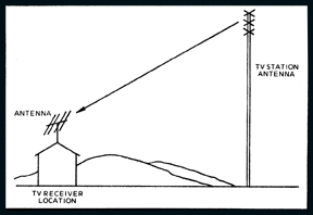 |
Figure 1. Exaggerated example of line-of-sight transmission. The receiving antenna can literally see the transmitting antenna. |
| The best reception is obtained when the signal from the transmitting antenna travels through an unobstructed line-of-sight path as shown in Fig. 1. As shown here, the receiving antenna can "see" the transmitting antenna. However, even when the receiving antenna can "see" the transmitting antenna, perfect reception will not necessarily result. |
|
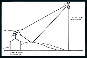 |
Figure 2. Example of multi-path reception. The TV signal travels directly from the transmitting antenna X to the receiving antenna Z. It can also travel from X to the ground at Y from where it is reflected to Z. |
| In Fig. 2. it is shown how the signal may travel directly from the transmitting antenna to the receiving antenna and at the same time the signal can travel to some other surface and then be reflected back to the receiving antenna. Therefore, when two signals from the same station are received at the receiving antenna via two paths of differing lengths, "ghostly" pictures with multiple images will result. |
|
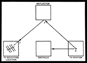 |
Figure 3. Example of reflected path reception. Because of the obstacle in the direct path between TV station X and receiving antenna Z, the signal travels to reflecting surface Y which reflects the signal to Z. |
| In many cases, particularly in large cities, the receiving antenna cannot "see" the transmitting antenna. Reception in such cases is possible via a reflected path as shown in Figure 3. Here it is shown that the signal from the television station, point X, travels toward the receiving antenna but encounters an obstacle. The signal from X also travels to another large obstacle to the side, point Y, from where it is reflected to the receiving antenna, point Z. The receiving antenna is pointed at Y so it can pick up the reflected signal from X. |
|
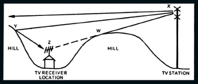 |
Figure 4. Reception in a valley may be poor or Impossible, particularly if the distance from the transmitter to the receiver is great. It Is possible that the refracted energy from point W will reach the receiving antenna at Z. If another hill beyond Z exists and is in line-of-sight of X, the signal might be reflected from Y to Z. |
| When hills intervene between the transmitting antenna and the receiving antenna, as shown in Fig. 4, it may not be possible to receive signals from the transmitting station. On the other hand, if the signal from X strikes a hill on the other side of the receiving location, point Y, and reflects a signal back to point Z, reception will be possible. |
|
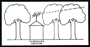 |
Figure 5. Trees absorb TV signals. If the antenna does not extend above the trees, significant absorption losses can result. |
| The waves transmitted by a television antenna are affected by foliage. If, as shown in Fig. 5, the signals must travel through trees, the trees will absorb some of the energy and cause less of it to be received by the receiving antenna. |
|
 |
Figure 6. Reception of TV stations in different directions may require the use of more than one antenna or a rotator. |
| When the stations to be received are in different directions, as shown in Fig. 6, it may be necessary to use separate antennas for receiving from different directions or a single antenna mounted on a rotator. When switching from station A to station B for example, the antenna is rotated so that it will point towards B and so on. |
|
 |
 |
 |
 |